Diplexers, taps and filters for TV FM and DAB
Subject list :
Diplexers including :
- Combining TV and FM / DAB
- Combining TV and satellite
- Combining modulated RF (e.g. CCTV)
- Combining signals from 2 TV aerials :
- - From 2 different transmitters
- - From the same transmitter
- Two signals in opposite directions !
- Diplexer built into a wall plate
Diplexers
A Diplexer is a form of "combiner/splitter" which only passes signals of certain frequencies through each leg. They are passive devices and as such don’t require any external power. Diplexers generally have a through “loss” of around 1.0 dB as opposed to that of a splitter/combiner which loses 3 to 4dB, and it’s important to remember that a diplexer (or splitter/combiner) loses as much when combining as when splitting. The loss figure for a diplexer will vary with the frequency, there will be a greater loss “on the shoulders” of the input frequency range on each leg. For example, on a CH38 TV/TV diplexer the loss at plus + / - one channel (i.e. CHs 37 and 39) would be about 4dB (or possibly more) whereas 5 channels away (e.g. CHs 33 and 43) it’d be down to approximately 1dB.
At the other end of each lead, another diplexer (e.g. a setback or surface plate type) should ideally be used to split the signal back into its constituent parts [mainly because a splitter has a significantly higher through loss] but if a feed from a satellite dish is involved a diplexer should definitely be utilised.
It should be noted that, if, at the input to your TV or radio, only one of the diplexed frequency bands is required (e.g. only FM not TV) it is not usually necessary to use a diplexer there because the unit’s own tuner should filter out the unwanted frequencies.
Perhaps the most common use of a diplexer is to combine the signals from a UHF(TV) aerial and a VHF(FM/DAB) radio aerial* onto one downlead, but note that not all diplexers accept FM and DAB signals, some have a filter and only accept FM or DAB. If required, this diplexed signal can then be fed through a distribution amplifier (or splitter if sufficient signal is present) to feed more than one point, but remember most mast head amps are only UHF compatible. Since it is rare to have to amplify FM (or even DAB) in order to split it our advice is to diplex the FM/DAB signal in after the TV mast head amp. In fact amplifying FM in particular can sometimes give worse results.
*An FM half wave dipole will actually work pretty well for both FM and DAB
Note that not all diplexers will pass DAB, particularly older ones.
If your mains distribution amp has separate FM/TV inputs (like our 4, 6 and 8 way amps) it already has a diplexer on the input. This is an important point because if you feed a combined FM/TV signal into the TV input the amp will only “accept” the TV component ! Furthermore not all models of amplifier which have TV/UHF + FM/VHF inputs will accept DAB on the latter input, the ones we sell do accept DAB. Incidentally when we checked the output of a Sky receiver with a spectrum analyser, it did pass FM & DAB, and they both emerged from RF1 and RF2. This information could be significant when planning your system.
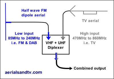
The graphic above shows a TV aerial diplexed with an FM half wave dipole. As discussed above the latter antenna can give good results on both FM and DAB so the resultant combined feed can supply TVs, and/or FM tuners, and/or DAB tuners. For more DAB signal (but less FM), a DAB antenna could be substituted for the FM aerial. For maximum FM and DAB signal a triplexer could be used with separate inputs for a TV aerial, an FM aerial and a DAB aerial.
It is also possible to diplex a signal from your satellite dish with one from your TV and/or FM/DAB aerial, then, down by the TV/Sky box, this can then be split out again to feed each unit. However, it must be noted that this combined signal cannot feed multiple satellite tuners simply by splitting it. If multiple feeds from a satellite dish to a number of “set top boxes” were required it would be necessary to use a multiswitch (and a Quattro LNB) which is outside the scope of this article.
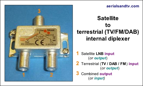
The fact that a diplexer can be utilised for satellite frequency signals is one of the most significant reasons why all cabling should use decent quality satellite grade cable and preferably with two cables to each point. You never know whether you, or someone who buys your house, will need to utilise existing wiring (possibly installed in the wall....) to carry signals from a satellite dish.
Any UHF frequency (e.g.the RF output from a CCTV camera modulator or a Sky box) can be diplexed together with a TV signal, but only if your transmitter is grouped and therefore has unused channels above or below its output, e.g. Crystal Palace. If your transmitter has no unused part of the band you would have to take your chances using a splitter in reverse, i.e. as a combiner. This does lose half the input signals and can result in signal interaction but will sometimes work fine. It should be pointed out that in the case of Sky it is far more usual to add the TV signal to the Sky RF output in the actual Sky box itself, the latter effectively has a built in combiner for this purpose. That said, if your system only has one cable from the aerial going into the loft (or wherever your distribution amp is) then using a diplexer to add the Sky output works quite well. In fact if the Sky input is on the low frequency leg of the diplexer then IR return path/Digi Link signals will pass (it did on ours anyway ! ) but only if the Sky box is connected to the low frequency leg because Digi link signals will not pass on the high leg.
More rarely a diplexer can be used to combine the signals from two TV aerials off two different transmitters (do not confuse this with a “phased array”). Although it is possible to just use a splitter "in reverse", there is the possibility of signal interaction and in addition the loss on a splitter type combiner is significantly higher than on a diplexer, in fact one loses the same amount of signal using a splitter as a combiner as one would using it as a splitter ! That said, it can sometimes work fine.
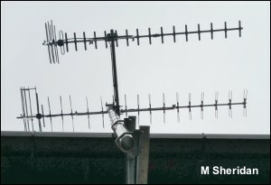
Anyway, you may be in a situation where you can get some MUXES OK off one transmitter, but some of the others better off another, or you might want the local news off a different transmitter than the one you normally get the best signal from*. Alternatively you may be in such a poor spot that at different times of the year the best signal is off different transmitters, trees are the most common cause of the latter. If the two transmitters outputs do not overlap in the band, and a diplexer with a suitable splitting frequency is available, both aerials outputs can be combined onto one downlead.
* For people only requiring one specific MUX from a different TV transmitter (e.g. the one with the local BBC news on it) many more combinations of aerials can use the CH38 diplexer.
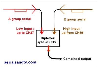
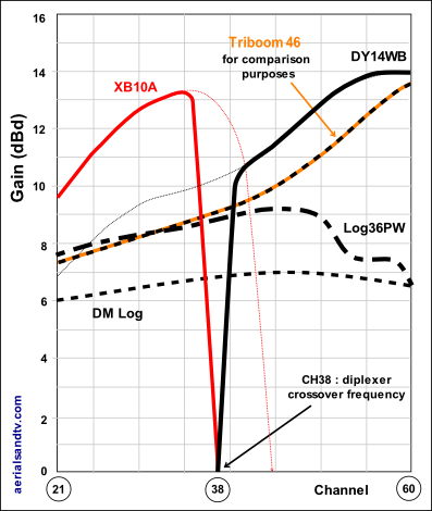
Alternatively a diplexer can be used to combine two aerials off the same transmitter, an example would be combining an A group and B (or K) group aerial off Mendip so you'd get increased gain off 5 of the MUXES but still get MUX 4, see Mendip's graph and also the graph below.
In the graphic on the right an A group aerial is shown diplexed with an E group or wideband and below is a graph of the gain curves resulting from the diplexing of a DY14WB with an XB10A using a CH38 diplexer.
See this article (written by a customer who undertook this type of install).
Resultant curve(s) from diplexing an A and a wideband aerial.
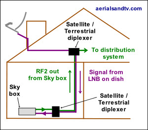
It may come as a surprise but using diplexers you can send two signals in opposite directions down the same cable (which is effectively what’s happening with the IR return/Digilink system). If you think about it this is no surprise because the signal isn’t DC, it’s AC and at different frequencies (as opposed to AC at the same frequency). What’s more loads of RF frequencies are flying about all round us and it all works swimmingly, but again, only if they aren’t the same frequency (or you’d get co-channel interference).
As an example you can send a TV (or FM or DAB) signal one way and a satellite signal the other using two UHF+ VHF/Satellite diplexers. Alternatively, using two UHF/UHF diplexers, you can send a modulated signal (e.g. from a Skybox or a CCTV) one way and the signal from your aerial the other way, although it should be pointed out this can only be done if you’re on a grouped transmitter.
In fact you could probably send signals in opposite directions using two splitter combiners but the losses would be greater and diplexers are filtered for the correct frequency range*, which is why I only bothered playing about with diplexers when I proved this two way traffic theory to myself in Sept 12.
* Which is why it’s preferable to use a diplexer to add to a modulated RF signal to a system as opposed to using the AUX input on a loft box or launch amp.
It’s like magic isn’t it ? ! ? In this example we’re sending a satellite IF frequency signal one way (down from the loft) and a UHF signal the other way, in this case the RF2 output from a Sky box but it could just as easily be any other modulated RF signal, e.g. from a CCTV.
An additional refinement of this is that the Digilink (IR Return) system will still work but only if the distribution amp is mains powered (like this one) as opposed to one which is remote powered by the Sky box. The reason is that the diplexer can only have power pass on the satellite leg if the LNB switching is to work correctly, thus the voltage sent to power the eyes (or the remote amp) can’t pass on the UHF leg. However, the IR return signal can pass, so we just need to add the voltage for the eyes from the mains powered amp.
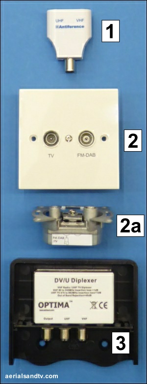
Three different types of diplexer, in this case they're all UHF/VHF, or, to put it the other way TV/FM + DAB. We also stock TV/TV and TV/FM/DAB, though technically the latter are triplexers.
1 - “Set back” diplexer (sold here). In some cases (not including satellite applications) a coax splitter may suffice though the through loss would be higher and the frequencies not filtered. All diplexers that we sell will accept DAB on the VHF/FM leg, not all of those in existence do, watch for that.
2 - Diplexer built into a surface plate (sold here).
Note 1 : We don’t recommend the use of "budget" unscreened wall plates.
Note 2 : not all diplexed wall plates pass DAB.
2a - View of the actual diplexer from the above surface plate. Note how there is only a terminal for one cable (clamp removed for clarity) input because it's a diplexer, and also the use of a screening can.
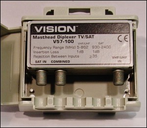
3 - “Mast Head” diplexer (sold here) with the front door of the weatherproof enclosure removed for clarity, the unit can also (for example) be screwed to a wall. The left hand connector is for the combined signal out [or in], and the right hand one the input [or output] for VHF (= FM /DAB) whilst the middle one is the UHF (TV) input [or output]. Note the use of a screening can. F connectors are included (if required) with our diplexers, splitters or amps.
Taps (no, not that kind of tap....)
Talking about taps and not a plumber in sight ?
(No change there then.......)
The explanation is that a tap is a type of splitter *. However, there is a significant difference between a splitter and a tap, the latter don’t evenly split the signal between the outputs. In fact, when it comes to taps, it’s all about the proportion of signal supplied to the main "through" output on the one hand, and to the "side" output(s) on the other.
Thus there are 2 loss figures quoted for a tap, its through loss, and its side loss. As an example an 8dB / 3dB tap would attenuate the side output(s) by 8dB, but the through output by only 3dB.
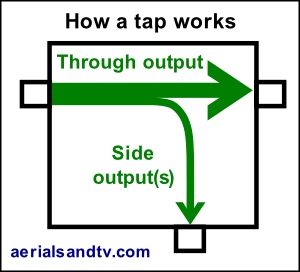
All this apparent complexity does have benefits though. Say you have an output from a one way mast head amp into the loft where you want to feed one point, then you need to feed an 8 way splitter at the other end of the house. Since an 8 way splitter would have a loss of 12dB, (plus the cable losses), a 15dB/1.2dB tap would be ideal because it’d feed the single point from its side port, then run the through outlet down to supply the 8 way splitter.
Graphic and details of a system utilising a mast head amp, a tap, and two splitters
Graphic and details of a larger distribution system utilising a power amp, taps and splitters
* Considering taps as a form of splitter is actually a bit simplistic because taps are internally very different from splitters. Taps have a higher return isolation than splitters, so some people say it’s technically beneficial to incorporate taps, or a mix of taps and splitters, into a system. Others say that taps have inferior impedance matching to (decent) splitters, so they only use them when they have to [particularly for satellite work], and then they try not to use more than one in series. I’d have thought that for most people there wouldn’t be much of a problem either way, especially for UHF/VHF work.
We stock three types of one way taps.
Filters for TV / FM / DAB
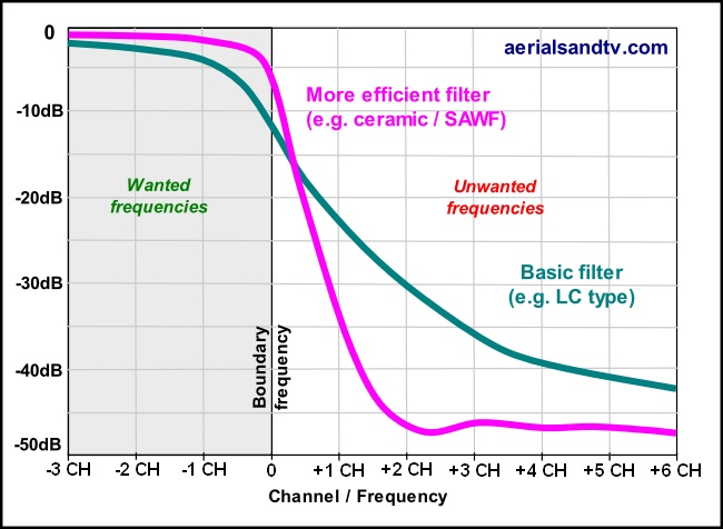
Filters should only let through signals of a certain frequency and, hopefully, reject all the others. Now this sounds simple enough, and it usually is, apart from near the edge of the wanted/unwanted frequency band. This is because no filter can give high rejection of one frequency and at the same time let through all, or even nearly all, of other very close frequencies.
In fact the further away from the edge of the wanted/unwanted boundary we go the more efficient the filter will be, the higher the attenuation of the unwanted frequencies and the lower attenuation of the wanted frequencies. The degree to which a filter is efficient at this boundary (i.e. the shape of the attenuation curve on the graph) can vary quite markedly, not all filters are equal ! As with most things, the more you pay, the better quality the product. LC (coil/capacitor) filters are reasonably priced but cannot match the sharper cut offs of more the sophisticated (read expensive) ceramic or SAWF filters which are more efficient, particularly near the boundary frequencies. Having said that, cheaper type LC filters are perfectly suitable for most jobs, provided you can be a little flexible about which frequency you need to use or filter out. As an example, if you have a B group filter accepting channels 34 to 53 the rejection of unwanted signals will increase rapidly the further you get below CH34 or above CH53. Similarly, though to a less extreme extent, the degree of attenuation of the wanted frequencies will be lower as you get further above CH34 or further below CH53. It should be noted that different models of filters, LC or otherwise, can have markedly different levels of performance……
Some say that placing a filter further away from the aerial (i.e. with a reasonable length of - correct impedance ! - cable between them), particularly a Log Periodic aerial, helps with matching. I’d have thought there might only be something in that if the matching between the aerial and filter is poor to start with.
However, there was one area where performance at the boundary frequency was paramount and that’s for 4G/5G filtering if you happened to be on a transmitter with MUXES above about CH46.
There are other reasons why use of a filter may be beneficial. For example, you may want some unused channels on your distribution system to add a modulated RF output from your Sky or CCTV. More usually you may be suffering from transmitter overlap. Filters can be very effective for both of these problems, but they can’t be used by everyone, you ’ll need to check if all the frequencies from your transmitter fall within a group.
Closing thoughts….. It’s the ultimate irony isn’t it ? After years of being told that everyone should be fitting wideband aerials to receive everything from CH21 to CH68, now many people suffer from transmitter overlap and, we’re told, may suffer from filtering problems with 4G/5GLTE, so they now need to buy filters to remove the unwanted transmissions !
NOTE : we don’t recommend high gain wideband or E group or T group aerials with alleged 4G/5G rejection characteristics because their gain drops off way before you get to the "unwanted frequencies".
In fact we don’t recommend any aerial with anything “built in” (e.g. a built in amplifier), because, by definition, you can’t remove it…..

